Voltage, resistance, and current
Ohm's law: V=IR.
Fact sheet
|
Name
|
Symbol
|
Definition
|
Unit
|
|
Voltage
|
V
|
A force that pushes the current through the circuit.
|
Volts (V)
|
|
Resistance
|
Ω
|
Friction that impedes the flow of current through the circuit, due to collisions.
|
Ohms (R)
|
|
Current
|
I
|
The time rate (△t) at which the charge (△q) moves past a particular point in a circuit.
|
Amps (A)
|
Current
Inorder to convert from electrons per second to amps, multiply by the charge of an electron in coulombs ()
Direct current: A circuit where the current flows in one direction. Used for short distance circuits because it is safer.
Alternating current: A circuit where the current flows alternate directions over time. Used for long distance circuits because of its higher voltage capacity.
Resistance
There are five things which can affect resistance, also as current is inversely proportional to resistance these five things will also change current but inversely.
|
Factor
|
Explanation
|
Equation
|
|
Length of wire
|
The longer, the wire, the more times the electrons hit the sides slowing down.
|
R∝L
|
|
Material
|
The lower the conductivity of the material(σ) the higher the resistance.
|
R∝1/σ
|
|
Wire thickness
|
The smaller the diameter(⌀) of, the wire, the more times the electrons bump into each other
|
R∝1/⌀
|
|
Temperature
|
Heating a wire makes the atoms in the wire vibrate increasing the number of collisions.
|
R∝T
|
Resistance formula: (resistance = resistivity * (length/current))
How to measure these values
|
Type of meter
|
What it measures
|
How it is connected
|
Ideal resistance
|
|
Voltmeter
|
Voltage
|
In parallel
|
Very high resistance, so electricity does not flow through it.
|
|
Ammeter
|
Current
|
In series
|
Very low resistance, so electricity flows easily through it.
|
Charge & Power
Charge: How something is affected by an electromagnetic field. A charge can be positive or negative and like charges will repel while opposite charges will attract.
Power: The rate of energy required to drive electrical current through a circuit. It proportional to the potential difference and to the electrical current that flows through the circuit.
Symbols, units and formula
|
Name
|
Symbol
|
Unit
|
Formula
|
|
Charge
|
Q
|
Coulombs
(C)
|
Q=IT
|
|
Power
|
P
|
Watts
(W)
|
P=IV
P=E/t
|
Series and parallel circuits
Series
Current: Is the same all around the circuit.
Voltage: Shared across each component. Components with higher resistance get more voltage
Resistance:
Parallel
Current: Split across each component
Voltage: The same for all components
Resistance:
Potential dividers
A potential divider is a circuit made of two or more resistors that allow us to tap off any voltage we want that is less than the battery voltage. You can imagine as using resistors to create a ratio of the voltages.
Formula:
- The input voltage (Vin) is the emf of the battery.
- The output voltage (VOut) is the voltage taken after the resistor
- R1 is a large resistor which takes the majority of the resistance
- R2 is a small resistor which takes the small amount of resistance.
Circuit Diagrams
|
Name
|
What it does
|
Symbol
|
|
Cell
|
A component which pushes the electric current (Voltage) from positive to negative.
|
 |
|
Battery
|
A component which consists of several cells.
|
 |
|
Resistor
|
A component which reduces the current flow.
(Almost every component is technically a resistor)
|
 |
|
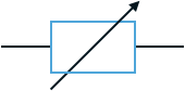
Variable resistor
|
A components which controls the current flow.
|
 |
|
Light bulb
|
A component which emits light, by heating up filament inside the bulb.
|
 |
|
Motor
|
A component which converts electrical energy into mechanical.
|
 |
|
Ammeter
|
A component which measures the current of a circuit.
|
 |
|
Voltmeter
|
A component which measures the potential difference across two points in a circuit.
|
 |
|
Switch
|
A component which breaks the flow of electrons in a circuit.
|
 |
Transformers
What are they?
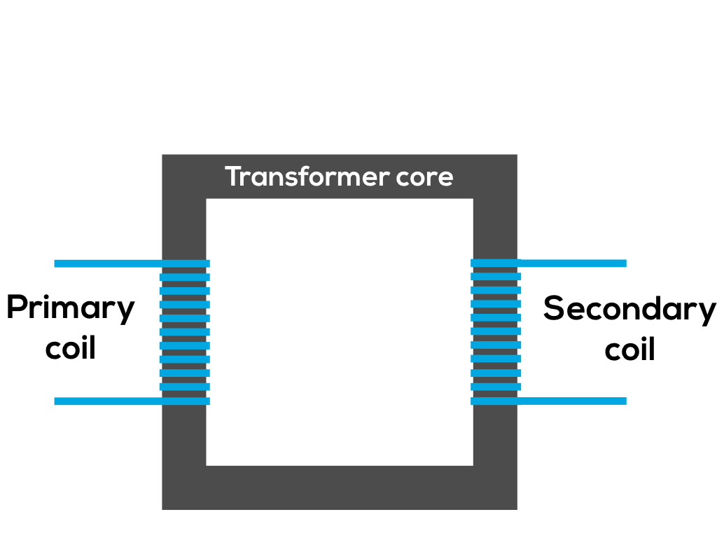
Transformers convert voltages from high alternating voltages with a low current to low alternating voltages with a high current or the other way around.
Transformers consist of a primary coil, secondary coil, and a transformer core. The primary coil is connected to the input Vp and the secondary coil is connected to the output Vs. The primary coil has Np number of coils and the secondary coil has Ns number of coils. The transformer core is usually made of iron.
Voltage formula
Or:
Power transfer: formula
Ip is the primary current. Vp is the primary voltage. Is is the secondary current. Vs is the secondary voltage.
Generators
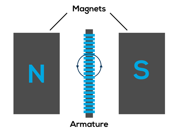
Generators are used to generate electricity by spinning a coil of wire in a magnetic field turning mechanical energy into electrical energy. They consist of a wire coiled around a core (usually iron) which can spin freely and can be small enough to fit in the palm of your hand or as big as a car.
How they work
Armature: The core and the wire wrapped around it
Generators generate electricity via the motion of the Armature relative to the magnetic field. This process is called electromagnetic induction. While the coil is spinning, the electrical current generated fluctuates and therefore these types of generator produces A/C.
Ways of generating electricity
In the past the coil was spun by using coal to boil water and using the steam to turn the coils. Now there are much cleaner ways to generate electricity, including using the potential energy of water in a dam and converting that into electrical energy by allowing the water to escape but using turbines capture the energy, or using wind to do the same thing.
Foundation, C. (2018). Generator. Retrieved from https://www.ck12.org/physics/generator/lesson/Electric-Generators-PHYS/
BBC - GCSE Bitesize: Generating a current. (2014). Retrieved from http://www.bbc.co.uk/schools/gcsebitesize/science/21c/sustainable_energy/generating_electricityrev3.shtml
Magnets
The magnetism in bar magnets cannot be turned off. This means that bar magnets are permanent magnets unlike electromagnets.
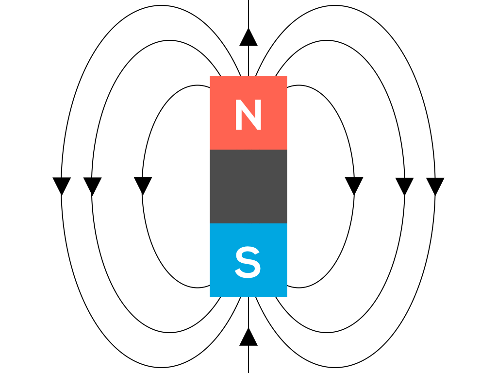
Bar magnets have two poles: the north pole (N) and the south pole (S). The north and south poles are opposite, therefore they repel each other.
Magnets are made from magnetic metals. These metals are nickel, cobalt and iron.

Magnetic field lines represent the magnetic fields of a magnet.
Editors- joeClinton - 989 words.
- - 10 words.
- Nhf1185 - 7 words.
- ar_yes - 67 words.
View count: 15386