Electromagnetic fields and forces
Magnetic fields are caused by the presence of magnets or moving charges.
- The symbol is B
- The unit for magnetic field strength is the Tesla (T)
- In a magnetic field line graph, the field direction is given by the direction of the field line and the magnitude is given by the field line density.
The direction of magnetic field line loops
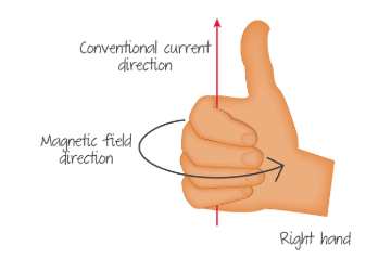
When a wire has a current flowing through it produces an electromagnetic field. This field is circular and the direction of the field line loops are determined by the Right-hand rule for magnetic field circulation.
If you place your right thumb in the direction of the current and then curl your fingers. The direction of your fingers in the direction of the magnetic force.
Magnetic field lines of current-carrying solenoid
In a current-carrying solenoid, the field lines are the same as that of a bar magnet. This is because if you apply the right-hand rule for magnetic field line direction to each individual wire then you'd see that the loop of one wire adds together with loops f the neighbouring wires to create one big loop.
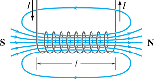
- If current moves anticlockwise then the end you are looking at is the north pole
- If current moves clockwise the end you are looking at is the south pole.
Magnetic force on a current-carrying wire (motor principle)
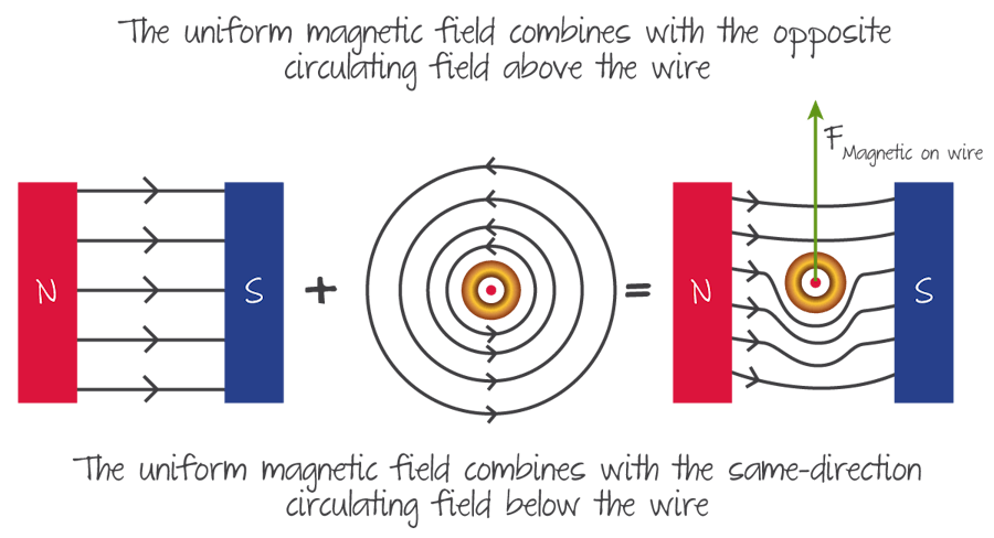
Since the electric current creates a magnetic field around the wire, if the wire is then placed in a different magnetic field it will experience a force, because magnets repel and attract each other.
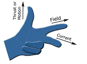
You use fleming's left-hand rule to determine this force.
- Point index finger in direction of the magnetic field (B)
- Point your ring finger in the direction of the current (I)
- And then Force is given by your Thumb.
Formula: \(F = B I L sin(\theta)\)
You can remember which goes with which by looking at data booklet seeing formula. The formula has force, field current, which is the correct order if using LHR.
Intuitive reasoning
Cross product version of the formula
The force is equal to the cross product of the electromagnetic field and the current time's wire length. The cross product is always perpendicular to the two vectors which are why the force is perpendicular. This should make sense if you do maths HL.
\(F = IL \cross B )
Magnetic force on moving charge
In this case, it is equivalent to the current except since there is no wire, you don't have current or wire length so you reformulate it with new variables.
We can convert current to charge per time \( I = \frac{q}{\Delta t}\) and length to velocity times time \(L = v \Delta t\). Then making these substitutes and cancelling out \( \Delta t\) we get
\(F = qvBsin(\theta)\)
The order of \(qv\) and \(B\) flips around, unfortunately, but on the bright side that now the correct order if you use the cross product
\(F = qv \times B \)
centripetal acceleration
This force causes the velocity to change which makes the charged particle rotate around a point
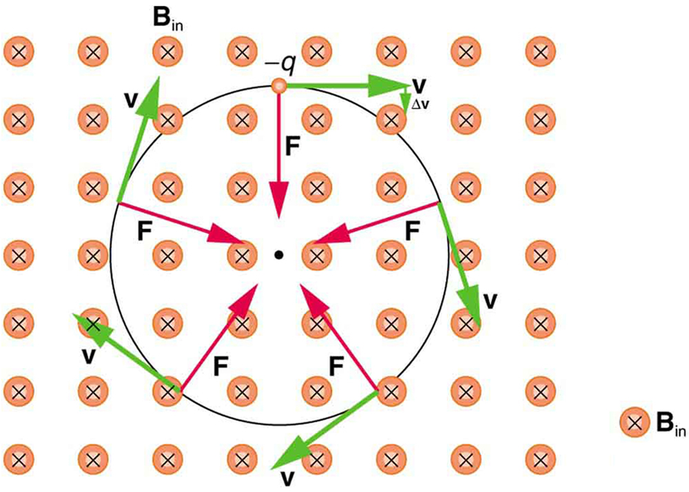
using the laws of centripetal acceleration if you know the radius of this loop you could determine the velocity of the particle.
Electromagnetic induction
Magnetic flux and magnetic flux linkage
Magnetic Flux
Flux: The total number of field lines in an area = electromagnetic field strength (B) normal to the surface \dot the area of the surface.\). Units = Webers (Wb)
Flux density: A measure of how close the field lines are together. This is equivalent to the electromagnetic field strength (B) Units = \(Wb \dot m^{-2}\)
\Flux (\phi) = BAcos(\theta)\)
\(\theta\) is equal to the angle between the normal to the plane and the electromagnetic field (B). So, if \(\theta\) is 0, the flux is greatest, and at 90° the flux is 0.
Flux linkage
Flux linkage: The total number of times field lines pass through an area. This is equal to the flux \(\phi\) multiplied by the number of coil lines.
\(Flux linkage = \phi N \)
Flux linkage is quite similar but the big difference is that it counts the number of times the field lines pass through an area not just the number of field lines, therefore this takes into account the number of coils their area. If an electromagnet has 50 turns in its wire then the flux linkage is 50 times the flux of one coil.
Inducing an emf
Faraday's law: Faraday's law states that the emf induced is equal to the negative rate of change in flux linkage. Therefore, if area, electromagnetic field strength or rotation change there will be an induced emf.
emf stands for electromotive force and in a circuit, it is the force which causes conventional current to flow. it has the symbol epsilon, \(\epsilon\)
\(Emf (\epsilon) = -N\frac{\Delta \phi}{\delta t}\)
Deriving different emf formulas
Depending on what variables are given in the question you might need to use different formulas.
| Formula | How it is obtained | When to use |
| \(\epsilon\) = -N\frac{\Delta BA cos(\theta)}{\Delta t} | Substitute formula for change in flux | use if you have a coil of wire where there is a change in the area, electromagnetic field strength, or rotation. |
| \(\epsilon = Bv\ell N\) | rate of change of area is velocity times length of wire, so you can replace \(\frac{\Delta A}{\Delta t} with \(v \ell\) | Use if you have a straight wire/conductor moving through an electromagnetic field. |
Fleming's right-hand rule
If a conductive wire moves through a magnetic field then the electrons contained within the conductor are also moving. Moving charges in an electric field induces an emf. To find this we use fleming's left-hand rule except we must remember that conventional current is in the opposite direction of the electrons.
For example, if the field is pointing into the page and the wire moves to the right, then the emf induced points downwards.
Instead of doing all this thinking, you can simply use fleming's right-hand rule, which is just the opposite of the left-hand rule
- Point thumb in direction of force /motion
- Point index in direction of the field (B)
- Then the ring finger gives the direction of induced emf/current

Lenz’s law
Lenz's law tells us that the induced emf acts in the direction such that the current induced will oppose the change that created it. This is useful for quickly figuring out the direction of induced emf, n multiple choice, instead of using fleming's right-hand rule.
The intuition behind this is that if the opposite was true then the new current would induce more emf in the same direction causing an acceleration. This goes against the conservation of energy and thus it has to oppose.
- If the conductor enters magnetic field induced current will create a force that opposes the motion.
- If the magnet enters the coil, the induced current will slow down magnet.
Power generation and transmission
Alternating current (ac) generators
- The generators work by having a coil which is spun inside a magnetic field.
- As the coil spins the flux changes because the area is at different angles to the magnetic field
- The rate of change of flux is greatest when the coil is parallel with the field (B), because it goes from a negative to a positive
- Thus there is an induced emf /current except it is alternating between negative and positive. This is alternating current

Average power and root mean square (RMS) values of current and voltage
Because the graph of emf and current is a sine wave the positives cancel out with the negatives so, the averages are 0
- Average voltage = 0
- Average current = 0
Average power
Average power is not 0, however because power is i*v , which = \(/P_{max} sin^2(\omega t)\)
Average power is \(\frac{1 }{2} P_{max} \) because the average value of a square sine wave is \(\frac{1}{2}\)
Root mean square
effective current and potential difference, also known as root mean square values (RMS), the required voltage/ current to get the same energy that dc would provide was used over the same time interval.
- \(V_{rms} = \frac{1}{\sqrt{2}}V_{max}\)
- \(I_{rms} = \frac{1}{\sqrt{2}}I_{max}\)
The derivation of these values is to take the square root of 1/2, as that is the average power.
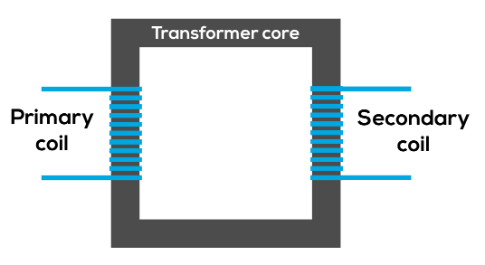
Transformers
Transformers are a pair of solenoids placed next to each other which share a magnetic core but are unconnected.
- Current flows in one solenoid called the primary coil which creates a magnetic field.
- The current is alternating so the changing magnetic field induces a current in the other solenoid, called the secondary coil
- The other solenoid has a different number of coils so the induced current is either stepped down or stepped up depending on the coil ratio.
- An iron core is used to improve the movement of flux between the coils.
why real transformers do not have 100% efficiency
- Joule heating: Energy lost from resistance in wires causing heat
- Magnetic hysteresis: The iron core stays magnetised even when there is no flux, so the change in flux, is not as great as it could be.
- Eddy currents: Some energy will be lost to "eddy currents" created in the core, which cause heat loss.
- Flux leakage: Eddy currents may be created in the surrounding metallic structure.
Converting AC to DC
Half-wave and full-wave rectifiers
Rectifiers are used to turn AC into DC. Which in other words means the current only moves in one direction.
- Half-wave: A diode is used which stops the current moving in the wrong direction, which essentially cuts the wave in half. This causes half of the energy to be lost to heat.
- Full-wave rectifier: A diode bridge is used which turns alternating current into direct current without loss of energy.
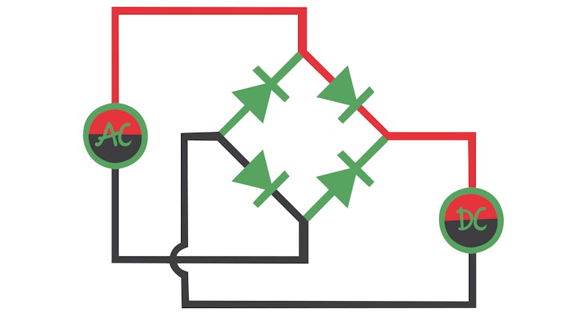
Diode bridge
A diode bridge is used to allow forward current to stay forward and to redirect backwards current into forwards. Unlike a single diode, this doesn't cut the wave in half, meaning the full energy can be conserved.
This requires 4 diodes.
How to draw the diode bridge
- Start by drawing a diamond
- Draw ac power source symbol (∿) then connect it to the top and bottom of the diamond.
- Next, connect the right side of the diamond to a load and then connect the load to the left side. Now there is a circuit.
- Next, add diodes pointing towards the right point. This stops current flowing back into the AC source.
- Next, add diodes pointing away from the left point This makes it so that current can't go the wrong way around.
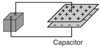
Capacitance
Capacitance
Capacitors are two plates separated by a distance, which will build upcharge. This charge cannot cross the plates, however, the charge builds up on one plate can induce an opposite charge on the other plate.
- Capacitance is the amount of charge that can be stored at a given potential difference. \( C = \frac{Q}{V}\)
- The charge keeps collecting until the potential difference is equal to the emf of the battery
- Capacitance is inversely proportional to distance and proportional to the area
\(C_{max} = \frac{\epsilon_0 A}{d}\) (\({\epsilon_0\) is the permittivity of free space)
Dielectric materials
- This is any material that is a poor conductor of electricity. Otherwise known as an insulator.
- Putting a dielectric material between the two plates increases the capacitance
relative permittivity
\(\epsilon_r = \frac{\epsilon}{\epsilon_0}\)
This is basically just a ratio between the permittivity of the dielectric material and the permittivity of air, it is always greater than 1.
Capacitors in series and parallel
formulas are in the data booklet
Capacitors in parallel
- \(C_{parallel}=C_1+C_2+.......\)
- Because area sum together
Capacitors in series
- \({1\over C_{series}}={1\over C_1}+{1\over C_2}+.......\)
- Because it effectively creates a bigger capacitor with further distance
Resistor-capacitor (RC) series circuits
This is a circuit with only a resistor, cell and capacitor
- Current decreases as you charge a capacitor because the increasing charge on the capacitor balances the incoming charge.
- Current decreases as you discharge a capacitor, as it builds up a charge in the load.
Time constant
- Time constant (t) = RC.
- defined as the time it takes for current to drop to \(\frac{1}{e}\) of the initial current. in other words, the capacitor is 63.3% charged.
Editors- joeClinton - 2070 words.
- CD_FER - 1 word.
View count: 9566